How to create your own rooms and worlds
The easiest way to create a new item is to modify an existing one.
Please note: Don't modify moove resources directly.
Instead make a copy and add your designer abbreviation / tag / label to the name.
Submit the label at shop search to check, if it is already in use by another designer.
The following examples are always using "My". Please replace it with your own label.
When you create your own shop, you will get package and distribution hints.
Please pay attention to Copyright, e.g. you may not use resources from other designers unless it is explicitly allowed.
Tools and documentation can be found in our Shop under Developer, in the Community menu section Designer and in moove Roomancer "Extras", "Developer Tools".
The sources of the room files can be found in the free moove Shop at "Developer", moove Room Sources. After unzipping with WinZip you will find the source files having the RDE extension.
To create a room file (*.ROM) from a source file (*.RDE), please do the following:
1) Activate the Roomancer test mode under "Extras" -> "Options" -> "Service".
2) Write into the Roomancer chat input line:
!ProcessRDE('<RoomFile.RDE>')
Instead of <RoomFile.RDE> please use the complete path to your existing RDE File. Please use single qoutes. Example:
!ProcessRDE('c:\download\RDE\Gallery.rde')
Please copy the ART folder with the design files (textures, 3D surfaces etc.) first, e.g. from c:\download\RDE\Gallery into the Roomancer folder (typically c:\moove).
Created room files are in the Roomancer folder ART\RMX
Please note:
ROM files only contain the 3D surfaces, e.g. you have to include textures (*.jpg and *.bmp) when creating MPZ package files and giving away. Please read here:
Pack your files into a MPZ file
Special moovePack hints for ROOMS
Please note: ROM file are not automatically transfered. Rooms cannot be visited, if the visitor does not have the ROM file in the ART\RMX folder.
Here at the tutorial you will learn the commands of the scripting language. This way you can design your own rooms. Please look below for explaining pictures.
Just edit the RDE source files with the :WordPad
editor for example.
ROOM
ROOM 0, "corridor"
Name of the room - this has to be the name of the RDE file, too.
START
START 0,0,700 FACE 3.14
Starting point for actors in the room (X,Y,Z)
X: Position of the point on the :X axis
Y: Position of the point on the Y axis (height above the ground)
Z: Position of the point on the Z axis
FACE: Direction of the actors face. Values are in :Radian
. 3.14 means rotated by half circle.
BACKGROUND
defines background with :RGB
values or :Texture
.
BACKGROUND RGB 60,60,60
defines the background color with :RGB
values for Red, Green, Blue - value range: 0-255
BACKGROUND TEXTURE "test.jpg", 200
"test.jpg": used Texture
200: Height
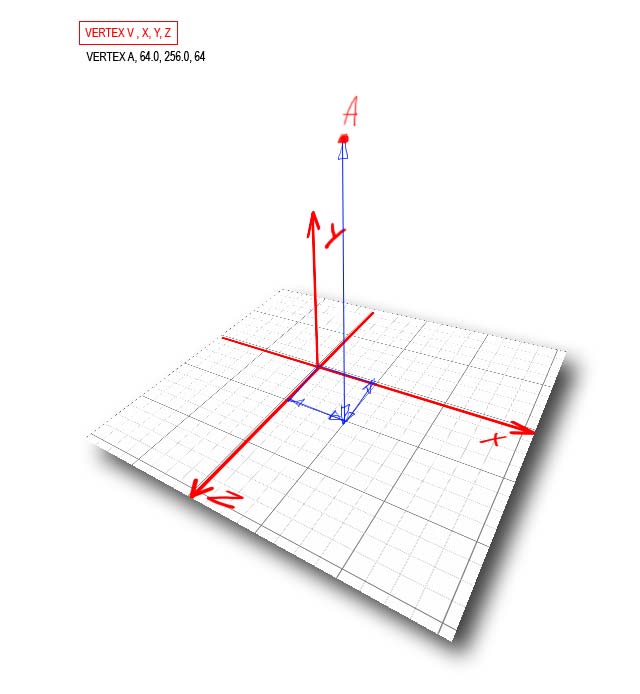
VERTEX
defines point as a :Vertex
VERTEX A X,Y,Z
A: Name
X,Y,Z: Position
MATERIAL
defines materials with :Texture
or :RGB
values.
MATERIAL 1 TEXTURE "test.jpg"
1: Name of the Material
"test.jpg": used Texture
MATERIAL 2 RGB 255,0,0
without Texture
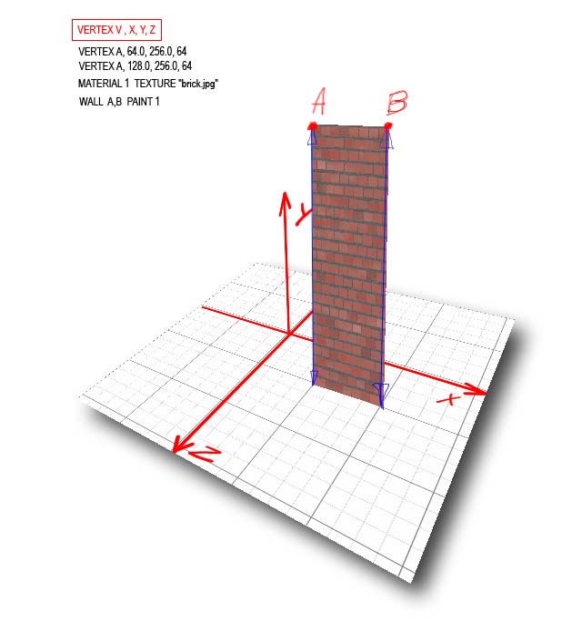
WALL
WALL A,B PAINT 1 NOSMAP
Walls always require 2 points.
The order of the vertices A,B or B,A defines the visible side of the wall - the other side is invisible.
PAINT names the used material.
NOSMAP "No Shadow Map": no pre fabricated shadow texture (BMP)
A missing NOSMAP causes the usage of a __PFW_....BMP file. Please take the name from the error message while testing.
You can create this BMP file with the "Lighting" option in the "Room Painter" for a wall of this size. You can modify the pre fabricated shadow texture with a paint program.
WALL A,B ZBUF PAINT 1 NOSMAP
ZBUF (:Z-Buffering
) enforces hiding of objects behind the wall.
Without ZBUF objects (other walls, too) behind the wall may be visible through it.
Caution! ZBUF is a burden to the system; please use it only when necessary, e.g. for separation walls and inwards turning walls.
Syntax: WALL vert_list [ ZBUF ] [ NOBLOCK ] [ NOCULL ] [ DISTLIGHT ] [ TRANSP r g b ] PAINT pt [ NOSMAP ] [ TILE a,b ] [SMAP name] [ DIFF d ]
NOBLOCK no blocking in front of the wall
NOCULL (please see at GROUP descritpion)
DISTLIGHT less light at distance
TRANSP 0,255,255 defines this RGB color as being transparent.
TILE 128,256 defines X- and Y- texture tiling.
SMAP "__smapspfl1" defines this shadow map texture file.
DIFF 0.5 takes only half of the ambient light
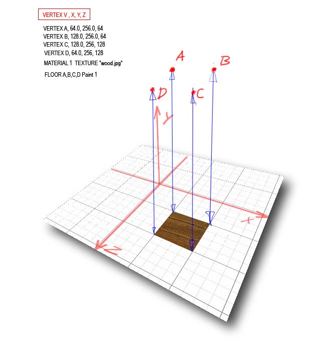
FLOOR
Define the floor with 4 points plus material (PAINT)
The Y values of the points are always treated as 0 when used for the floor; this way you can use wall points for the floor as well.
FLOOR A,B,C,D Paint 1 NOSMAP
Defining several floor sections enables better structuring of the rooms and better re-usage of textures.
[ TILE a,b ] [SMAP name] [ DIFF d ] syntax like WALL
CEILING
Ceilings, syntax like FLOOR
CEILING A,B,C,D Paint 1 NOSMAP
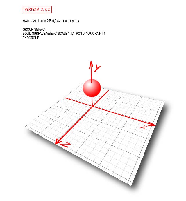
GROUP
you can add fixed 3D objects with the "Group" command.
Please note: Groups are not user paintable when using the room painter for walls, floor and ceiling.
GROUP "test"
NoClimb
SOLID SURFACE "test" SCALE 1, 1.12 ,1.4 POS 0, 50, -10 PAINT 1 //NOCULL
ENDGROUP
NoClimb: Actors don't climb the object but pass through or below (group above the floor).
SOLID SURFACE "test": names the wanted SRF file (:Surface
= structure).
SCALE 1, 1.12 ,1.4:
Width, height and depth of the object in world coordinates:
X=100
Y=112
Z=140
POS 0, 50, -10:
Position within the world:
X=0
Y=50
Z=-10
PAINT 1:
MATERIAL 1 is used to paint the object.
NOCULL: :Culling
is an optimization for structures with closed structure.
NOCULL disables this optimization for open structures and slows the visualization.
Group with rotation:
GROUP "test2"
ROTATE 0,3.14,0
NoClimb
SOLID SURFACE "test" SCALE 2, 3.5 ,1 POS 0, 1090, 0 PAINT 1
ENDGROUP
Rotation X,Y,Z in :radian
Syntax: GROUP name [ NOCLIMB ] [ DRAG ] [ ORIGIN X Y Z ] [ MATERIAL ] [ VERTEX ]
[ POLYGON ] [ LINE ] [MESH] [ SOLID ] [ SPRITE ][ SCALE X,Y,Z ][ SHADED Light Index [ CAST ] CastShadow ]
[ ROTATE X,Y,Z Vector ] [ POS Vector ] [ SET ORIGIN TO Vector ] [ TOREG region, x, z, direction ] ENDGROUP
NOCLIMB: Actors cannot climb it
DRAG: you can drag items to the group
ORIGIN X Y Z: origin vector of the group
POLYGON list of VERTEX A X,Y,Z | VERTEX A X,Y,Z (U,W) texture positions [ TRANSP r g b ] PAINT pt [ NOCULL ]
LINE VERTEX A X,Y,Z, VERTEX B X,Y,Z, width d [ TRANSP r g b ] PAINT pt
MESH [ PLANE v0, v1, v2, v3, nUDiv, nWDiv | BOX vMid, w, l, h | PYRAMID vMid, w, h ], width d [ TRANSP r g b ] PAINT pt
SOLID [ BOX vMid, w, l, h | PYRAMID vMid, w, h | SPHERE vMid, r, q | SURFACE "SurfName" [ SCALE x,y,z ] [ POS x,y,z ] [ AT vertex ] [ TRANSP r g b ] PAINT pt [ NOCULL ]
SPRITE spr_name AT x,y,z [SIZE d] [ DIR d ] [ PHASE_construct ]
PHASE_construct: PHASE n | PHASE n0 - n1 IN secs | PHASE n0,n1,n2 IN secs
SCALE X,Y,Z
SHADED Light Index [ CAST ] CastShadow
ROTATE X,Y,Z Vector
POS Vector
SET ORIGIN TO Vector
TOREG region, x, z, direction
BLOCK
BLOCKING LINES
stops actors
BLOCK 100,100, -100,200
BLOCK X start,Z start, X end,Z end
REGION
Only for cameras
defines regions to be seen by cameras
Optimizes the speed of visualization
Region X, A,B,C,D
X: Name
A,B,C,D: Points
Region X1, A,B,C,D SEES X1,X2,X3,X4
X1: Name
A,B,C,D: Points
X1,X2,X3,X4: List of Regions which can be seen from Region X1
CAMERA
The example defines a camera only seeing region X (rendering :3D computer graphics
).
Everything outside of this region isn't visible, when this camera is active.
CAMERA -1799, 847,2453 TO -1795,846,2448 SEES X
CAMERA from :coordinates
TO coordinates SEES X
Please keep distance to walls.
WALKAREA
defines the walkable area on the floor.
WALKAREA A,B,C,D
A,B,C,D: Vertices at the edges - similar to REGION
INIT
defines a function to be called on Init
INIT "ShrinkRoomInit"
DOORS code in the related ShrinkRoom.uni file:
FUNCTION ShrinkRoomInit(nSpaceIdx)
FOR n := 1 TO 7
OwnerInteract(#AS_Shrink)
NEXT n
EXIT
defines a function to be called on Exit
EXIT "ShrinkRoomExit"
DOORS code in the related ShrinkRoom.uni file:
FUNCTION ShrinkRoomExit(nSpaceIdx)
OwnerInteract(#AS_Reset)
Illustrations
Help and Contact | powered by |